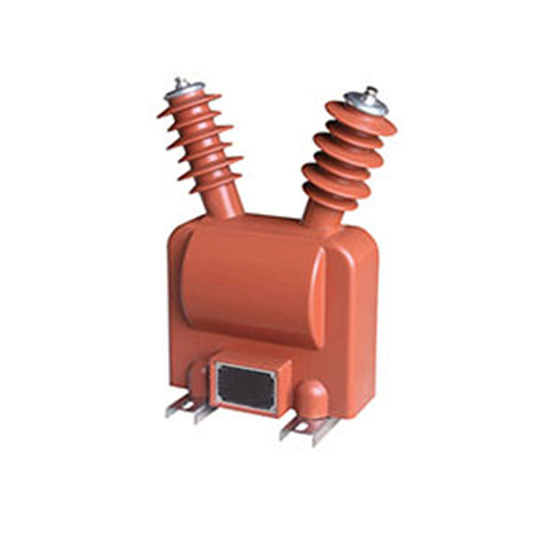
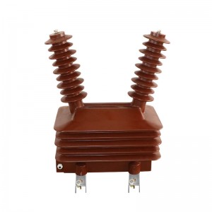
JDZW2-10 Voltage Transformer
Conditions of Use
1. Ambient temperature: -25℃~+40℃;
2. Contamination level: Ⅳ level;
3. Comply with GBl207-2006 “Voltage Transformer” standard.
Principle
When the voltage transformer is in normal operation, the three-phase voltage of the power system is symmetrical, and the sum of the three-phase induced electromotive force on the third coil is zero. Once the single-phase grounding occurs, the neutral point will be displaced, and the zero-sequence voltage will appear between the terminals of the open triangle to make the relay act, thus protecting the power system. When zero-sequence voltage appears in the coil, zero-sequence magnetic flux will appear in the corresponding iron core. To this end, this three-phase voltage transformer adopts a side yoke core (when 10KV and below) or three single-phase voltage transformers. For this kind of transformer, the accuracy of the third coil is not high, but it requires certain overexcitation characteristics (that is, when the primary voltage increases, the magnetic flux density in the iron core also increases by a corresponding multiple without damage).
Why do you need to change the voltage on the line? This is because according to the different conditions of power generation, transmission and electricity consumption, the voltages on the lines are different in magnitude, and the difference is very different. Some are low-voltage 220V and 380V, and some are high-voltage tens of thousands of volts or even hundreds of thousands of volts. To directly measure these low-voltage and high-voltage voltages, it is necessary to make corresponding low-voltage and high-voltage voltmeters and other instruments and relays according to the size of the line voltage. This will not only bring great difficulties to the manufacture of the instrument, but more importantly, it is impossible and absolutely forbidden to directly make a high-voltage instrument and measure the voltage directly on the high-voltage line.
Precautions
1. Before the voltage transformer is put into operation, the test and inspection shall be carried out according to the items specified in the regulations. For example, measuring polarity, connection group, shaking insulation, nuclear phase sequence, etc.
2. The wiring of the voltage transformer should ensure its correctness. The primary winding should be connected in parallel with the circuit under test, and the secondary winding should be connected in parallel with the voltage coil of the connected measuring instrument, relay protection device or automatic device. At the same time, attention should be paid to the correctness of the polarity. .
3. The capacity of the load connected to the secondary side of the voltage transformer should be appropriate, and the load connected to the secondary side of the voltage transformer should not exceed its rated capacity, otherwise, the error of the transformer will increase, and it is difficult to achieve the correctness of the measurement.
4. No short circuit is allowed on the secondary side of the voltage transformer. Since the internal impedance of the voltage transformer is very small, if the secondary circuit is short-circuited, a large current will appear, which will damage the secondary equipment and even endanger personal safety. The voltage transformer can be equipped with a fuse on the secondary side to protect itself from being damaged by a short circuit on the secondary side. If possible, fuses should also be installed on the primary side to protect the high-voltage power grid from endangering the safety of the primary system due to the failure of the transformer’s high-voltage windings or lead wires.
5. In order to ensure the safety of people when touching measuring instruments and relays, the secondary winding of the voltage transformer must be grounded at one point. Because after grounding, when the insulation between the primary and secondary windings is damaged, it can prevent the high voltage of the instrument and the relay from endangering personal safety.
6. Short circuit is absolutely not allowed on the secondary side of the voltage transformer.


